I had to make a new change to the system that I thought I should share for safety.
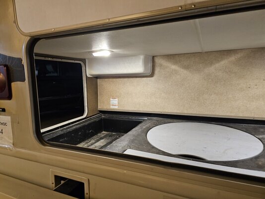
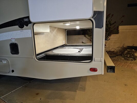
Recently I added a method of connecting the 12 volt supply to a external load. In this case the Macerator pump by way of an extension and a connector.
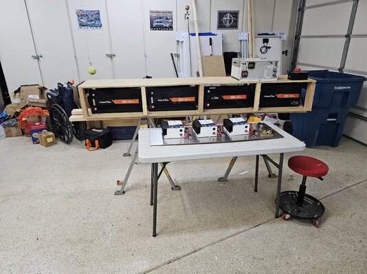
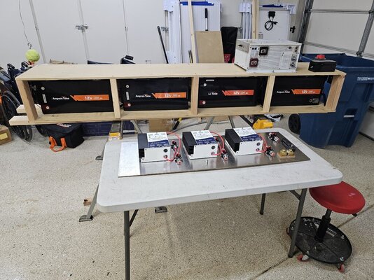
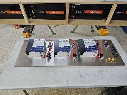
As I was working on adding this capability, I found that my disconnect switch from the battery bank to the Invertor was welded in the closed position, which prevented me from shutting off the battery connection.
I was able to disconnect the switch by removing the nuts from the switch.
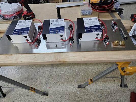
The standard disconnect switch is rated at 275 amps and I replace it with one rated at 600 amps.


 RV fires go SO fast.